Development of Wireless Sensors to Monitor Corrosion in Civil Infrastructure Systems
(A)
Research Objectives:
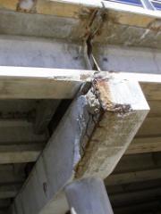
Deterioration of concrete structures due to corrosion of the embedded reinforcement is a worldwide problem. Structures exposed to marine environments or deicing salts are particularly at risk. Because the steel reinforcement cannot be inspected visually, corrosion often remains undetected until extensive cracking or spalling has occurred (Fig. 1). This damage can reduce the service life of the structural member and can create a safety hazard as pieces of concrete can fall on unsuspecting motorists and pedestrians. Early detection of corrosion within reinforced concrete structures would give the owner the opportunity to remediate the situation before structural damage occurs.
 Under
ideal conditions, reinforcement embedded in concrete will not corrode. Concrete has a pH of approximately 12.5, and
this provides a protective environment for the steel reinforcement because a
thin film of passivating iron oxide forms on the surface of the steel
(Hausmann, 1965). However, two
processes lead to a breakdown of the passivating film and initiation of
corrosion: firstly, an acidic
environment develops when carbon dioxide from the air mixes with water in the
concrete pores (carbonation) that removes the passivating layer; and secondly,
the passivating layer can become permeable due to the presence of chloride ions
that penetrate into the concrete from deicing salts and marine environments. The volume of the corrosion products can be
five to ten times the volume of the original steel. This volumetric increase causes internal pressures in the
concrete, which leads to cracking and spalling of the concrete cover (Fig. 1). If corrosion is detected in its early
stages, actions may be taken to regenerate the passivating layer on the surface
of the reinforcement or seal the surface of the concrete to prevent chloride
ion penetration. However, once
corrosion has progressed to the stage where structural damage has occurred,
repairs are much more costly, because the damaged concrete must be replaced.
Under
ideal conditions, reinforcement embedded in concrete will not corrode. Concrete has a pH of approximately 12.5, and
this provides a protective environment for the steel reinforcement because a
thin film of passivating iron oxide forms on the surface of the steel
(Hausmann, 1965). However, two
processes lead to a breakdown of the passivating film and initiation of
corrosion: firstly, an acidic
environment develops when carbon dioxide from the air mixes with water in the
concrete pores (carbonation) that removes the passivating layer; and secondly,
the passivating layer can become permeable due to the presence of chloride ions
that penetrate into the concrete from deicing salts and marine environments. The volume of the corrosion products can be
five to ten times the volume of the original steel. This volumetric increase causes internal pressures in the
concrete, which leads to cracking and spalling of the concrete cover (Fig. 1). If corrosion is detected in its early
stages, actions may be taken to regenerate the passivating layer on the surface
of the reinforcement or seal the surface of the concrete to prevent chloride
ion penetration. However, once
corrosion has progressed to the stage where structural damage has occurred,
repairs are much more costly, because the damaged concrete must be replaced.
The most common existing method for detection of corrosion in reinforced concrete structures is the measurement of small electric fields at the surface (ASTM C876-99). These electrostatic fields are the result of the electrochemical corrosion of the steel reinforcing members; the currents produced by the electrochemical reactions generate voltages that are then detected remotely. By making measurements over the whole surface, corroding and non-corroding locations can be a distinguished. Unfortunately, this method is subject to many interfering effects, such as the surface condition, and the moisture, carbonate, and salt content, of the concrete. It is also very difficult to obtain corrosion rate information using this method (Scannell, et al., 1996).
Other remote sensing approaches include acoustic emission monitoring (Zdunek et al., 1995), electrochemical impedance spectroscopy (EIS) (Davis et al.), and time domain reflectometry (Liu et al., 1999). Again, all these methods can suffer from significant interfering effects, making it difficult to localize and un-ambiguously identify specific effects.
The interference problems mentioned above are quite representative of a general problem in structural health monitoring: the low confidence in the relation between measurands and actual structural state. If a remote sensing approach (e.g., an acoustic or electromagnetic signature) is used this can be a significant problem, and is a fundamental difficulty in most inverse problems. Unless a complete set of measurements is made, the inverse solution is not unique. In most practical cases it is in fact extremely difficult to even know when a complete set has actually been measured. This problem is compounded by the low contrast in many structural “imaging” techniques (here we use the term “imaging” in the very broad sense of a generalized picture of the state of a system).
One way to avoid the inverse ambiguity is to use point sensors. In a general sense, a point sensor could be defined as a device that samples a small enough volume that the relation between transducer response and state are nearly unique. The risk is now the potentially large number of point sensors that might be required, and the loss of the simplicity of making “remote” measurements. In addition, for point sensors embedded in a structure, a critical constraint is the power required by the transducer and the method by which the sensor is interrogated. In many cases the structural element whose state must be determined is not physically accessible. One solution is to actually “wire” the sensor to an external connection, allowing almost any amount of power to be delivered to, and almost arbitrarily complex data to be transmitted from, a transducer. There are obvious problems with such wired approaches. For the case of most civil engineering structures, it is unlikely that the wires would survive the normal construction process. The alternative is a wireless communications link.
In a truly wireless system there also should not be any external power connection; one option is to power the transducer using a battery (with the battery embedded in structure along with the sensor). Power consumption in high data rate communications can be quite high, so power supply capacity and battery lifetime would be major constraints. Regardless, wireless data transmission and power coupling appear to be the preferred method for embedded point sensors.
It may be that a hybrid of remote and point sensing could circumvent problems associated with either one individually. For instance, a technique used in medical imaging serves as an excellent example: in an arteriogram a contrast enhancement “dye” is injected into the circulatory system to allow better visualization in the x-ray image. This could be viewed as the addition of “point sensors” that are interrogated using a remote sensing method. In the most general sense, then, our objective is the development of new “contrast enhancement sensors” embedded in structural elements that improve our ability to invert the results of remote measurements to determine the state of the structure. Two obvious remote sensing techniques are electromagnetic and acoustic measurement. Hence, the contrast enhancement sensors might be designed to produce either a unique electromagnetic or acoustic signature that changes in response to the state of the structural elements. Here we propose the development of sensors, probed using electromagnetic fields that produce enhanced sensitivity to corrosion processes in civil structures.
(B)
Methodology
An example of a low cost, simple device that can be interrogated remotely is the Electronic Article Surveillance (EAS) sticker. The sticker contains two printed elements on an adhesive tape: a conductive loop that produces an inductance, and a capacitor (Fig. 2). Typical dimensions of the sticker are about 1½ by 1½". In this “wireless” device, the power and data coupling is done remotely, using an ac source and driving coil (frequently referred to as an antenna) that inductively produces an ac current in a receiving antenna connected to the sensor system. The receiver uses this induced current to operate the transducer and produce a response that is broadcast back to the transmitter. The circuit in an EAS tag is designed to be resonant: The EAS sticker can be visualized as a bell that rings at a characteristic frequency, but is not excited by electromagnetic energy at other frequencies.
 These
devices provide a simple means of detecting one state of a system: if the loop
and capacitor remains intact then a transceiver can remotely detect its
presence, but if anything disrupts the circuit, the “bell” will no longer ring
at its characteristic frequency. This
approach provides essentially one bit of information about the monitored
point. The resonance provides the
“contrast enhancement” that allows high signal-to-noise and localizes a remote
electromagnetic response to one specific site and state. Significant work is required to transfer
this technology to the proposed application of detecting corrosion of steel
embedded in a structural element, but the basic development work for the
technology has been completed, and the technology has proven to be robust and
cost-effective.
These
devices provide a simple means of detecting one state of a system: if the loop
and capacitor remains intact then a transceiver can remotely detect its
presence, but if anything disrupts the circuit, the “bell” will no longer ring
at its characteristic frequency. This
approach provides essentially one bit of information about the monitored
point. The resonance provides the
“contrast enhancement” that allows high signal-to-noise and localizes a remote
electromagnetic response to one specific site and state. Significant work is required to transfer
this technology to the proposed application of detecting corrosion of steel
embedded in a structural element, but the basic development work for the
technology has been completed, and the technology has proven to be robust and
cost-effective.
![]() Figure 3 illustrates the electrical
equivalent circuit of an EAS tag, including parasitic coupling to other metal
elements within a reinforced concrete structure, and the associated
transmitter/receiver. This figure also
illustrates a method for monitoring a set of discrete states of the
system. Each state sensor switch would
actuate in response to some specific state, thus shifting the resonance
frequency of the tag. By measuring the
changes in resonance frequency the state of the switches would be determined.
Figure 3 illustrates the electrical
equivalent circuit of an EAS tag, including parasitic coupling to other metal
elements within a reinforced concrete structure, and the associated
transmitter/receiver. This figure also
illustrates a method for monitoring a set of discrete states of the
system. Each state sensor switch would
actuate in response to some specific state, thus shifting the resonance
frequency of the tag. By measuring the
changes in resonance frequency the state of the switches would be determined.
One issue for corrosion monitoring in
civil structures is the lack of rigid specifications of material properties for
typical reinforcement. For example,
ASTM requirements for steel strand (ASTM A 416, 1999) and wire (ASTM A 82, 1997
and ASTM A 496, 1997) state that the base material must be steel but do not
limit the chemical composition of the steel in any way. ASTM requirements for reinforcing bars (ASTM
A 615, 2000) limit the phosphorus content to 0.06%, but do not limit percentages
of carbon, manganese, or sulfur. Limits
are placed on the chemical composition of low-alloy reinforcing bars (ASTM A
706, 2000), because welding of these bars is permitted, but this grade of
reinforcement accounts for less than 1% of the reinforcing steel manufactured
in the US.
Another possible state switch would consist of two non-corroding electrode
rings that surround a steel reinforcing bar at the location of concern (Fig.
4). The electrodes would be
capacitively coupled to the steel on one end, and connect to the resonant tag
on the other. As the steel corrodes the probe circuit impedance would change,
hence changing the overall resonance of the tag. This should produce a more
continuous signal than the corroding wire switches.
Regardless of the solutions to the problems presented above, a fundamental hurdle will always be cost. Technological feasibility clearly does not guarantee actual use. If the cost of a “remote sensing” system or of installing structural health monitoring devices is too high, the systems will not be used. Hence, integral part of our sensor development will include consideration of manufacturing costs, cost of installation, and cost of maintenance.
Expected Results / Time Line:
· Determine basic components of sensor (corroding elements, methods for waterproofing EAS tag where needed, logical limits for the number of state switches) (months 1-6 of project).
· Develop electromagnetic and circuit models of the system (months 1-6 of project).
· Evaluate limits of wireless communication through concrete (corrosion starts close to the surface, so the sensing range will not need to be deep - probably 2 to 4 in.) (months 1-6 of project).
· Accelerated corrosion tests (use traditional half-cell potentials to monitor wire and rebar corrosion - this is a follow up to task 1) (months 6-12 of project).
· Design portable transmitter/receiver for wireless interrogation of sensors (months 13-18 of project).
· Validation tests on large-scale specimens in the laboratory (use the existing salt water bath at FSEL (months 19-24 of project).
· Field installation (ensure that sensors can survive construction process) (months 19-24 of project).
(C) Research Personnel
Dean Neikirk is a professor in Electrical & Computer Engineering, holding the Cullen Trust for Higher Education Professorship in Engineering. He established the Microelectronics Fabrication Teaching Laboratory at UT-Austin, providing students with hands-on experience in integrated circuit fabrication. He supervises students on projects involving integrated circuit fabrication and materials, new electromagnetic devices, and micro-machined sensors. Sharon Wood is a professor in Civil Engineering. Her research and teaching interests are related to the behavior of civil structures. She is also studying the use of composite materials to strengthen existing reinforced concrete bridges and conducting fatigue tests to evaluate damage to stay cables.
(D) Technology Transfer
We have extensive experience working with industry, including a transfer of our chemical sensor technology to a new start-up company. Since cost, manufacturability, and actual installation are key goals of this proposal, we intend to work closely with potential technology transfer partners to ensure the sensors developed can be used in a cost-effective manner.
(E) Institutional Commitment / Additional Support
Wood and Neikirk are co-investigators on an NSF-sponsored project for the development of new wireless sensors used to detect cracks in structural steel connections. The Texas Department of Transportation currently supports research at UT-Austin to develop novel surface treatments to retard chloride ion penetration in reinforced concrete bridges. Facilities for accelerated corrosion testing, and extra test specimens, will be available for use in this project. Wood’s and Neikirk’s research labs are at the Pickle Research Campus. Neikirk’s research is conducted at the Microelectronics Research Center with 12,000 sq. ft. of clean room space for fabrication; his group has the equipment necessary to fabricate and characterize the devices proposed here. For testing of sensors imbedded in structures, Wood conducts research at the Ferguson Structural Engineering Laboratory, an integrated research and teaching facility, under the direction of the Department of Civil Engineering. The main lab occupies 45,000 sq. ft with a 400 ft by 48 ft structural test area.
(F)Student Involvement and Training
Opportunities in Science and Engineering
This program provides an ideal environment for the education and training of students at the undergraduate and graduate levels in a highly interdisciplinary area that encompasses materials science, sensor fabrication, and application to real-world structures. The involvement of undergraduates exposes students at an early stage to the possibility of interdisciplinary work, and serves as an opportunity for graduate students to gain critical mentoring skills.
(G) Budget Justification
The vast majority of the equipment and infrastructure required to complete the proposed research is already in place. One equipment item needed is the swept frequency transmitter/receiver necessary to “read” the tags proposed here. The budget provides partial summer salary for the principal investigators, as well as support for three graduate students and one undergraduate. The supplies requested are necessary for the fabrication of prototype EAS tags in our Microelectronics Center. The other support personnel requested are for partial technician support at the Ferguson Lab, necessary to support the construction of reinforced concrete test members.
(H) References
ASTM A 82 (1997). “Standard Specification for Steel Wire, Plain, for Concrete Reinforcement.” Annual Book of ASTM Standards.
ASTM A 416 (1999). “Standard Specification for Steel Strand, Uncoated
Seven-Wire for Prestressed Concrete.” Annual Book of ASTM Standards.
ASTM A 496 (1997). “Standard Specification for Steel Wire, Deformed,
for Concrete Reinforcement.” Annual Book of ASTM Standards.
ASTM A 615 (2000). “Standard Specification for Deformed and Plain
Billet-Steel Bars for Concrete Reinforcement.” Annual Book of ASTM
Standards.
ASTM A 706 (2000). “Standard Specification for Low-Alloy Steel Deformed and Plain Bars for Concrete Reinforcement.” Annual Book of ASTM Standards.
ASTM C 876 (1999). “Standard Test Method for Hall-Cell Potentials of Uncoated Reinforcing Steel in Concrete.” Annual Book of ASTM Standards.
Davis, G.D., Dacres, C.M., Shook, M., and Wenner, B.S. “Electrochemical In-Situ Sensors for Detecting Corrosion on Aging Aircraft,” http://www.daccosci.com/FASTPAP.htm.
Hausmann, D.A. (1964). “Electrochemical Behavior of Steel in Concrete,” Journal, American Concrete Institute, Vol. 61, No. 2, pp. 171-188.
Liu, W., Hunsperger, R., Folliard, K., Chajes, M., Barot, J., Jhaveri, D., and Kunz, E. (1999). “Detection and Characterization of Corrosion of Bridge Cables by Time Domain Reflectometry,” Proceedings, SPIE International Symposium on Non-destructive Evaluation Techniques for Aging Infrastructure & Manufacturing, Newport Beach, California. Vol.3587, pp. 28-39.
Scannell, W.T., Sohanghpurwala, A.A., and Islam, M. (1996). “Assessment of Physical Condition of Concrete Bridge Components,” FHWA-SHRP Showcase Participant’s Workbook, Concorr, Inc., Ashburn, VA.
Zdunek, A.D., Prine, D., Li, Z., Landis, E., and Shah, S. (1995). “Early Detection of Steel Rebar Corrosion by Acoustic Emission Monitoring,” Proceedings, CORROSION95, Paper No. 547, NACE International – The Corrosion Society.